Coordinate Systems
The definitions and specifications of the different coordinate systems related to SURE are described below.
Input/output Coordinate System
SURE expects the camera orientation and/or LiDAR point clouds to be defined in the same Cartesian coordinate system. If your input data is defined in a projected coordinate system please see the article on Earth Curvature.
You can specify the coordinate system of your data during the project set up or in the Advanced Configuration Panel. See Georeferencing and Tiling for details.
All output results are generated in the same coordinate system as the input data except for Cesium and slpk mesh formats, which require a specific coordinate system. In this special cases, the project must use a coordinate system for which transformations are supported. To make it possible to generate these output formats based on different vertical datums, SURE supports shifting the height of the mesh.
Note, if a coordinate system is not specified, a local coordinate system is established based on input data and the cesium or slpk mesh formats can’t be generated.
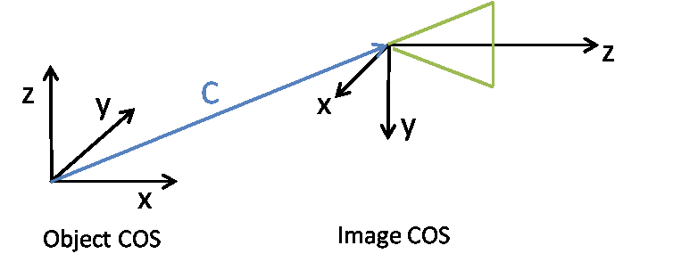
Camera Coordinate System
Assume an object point X (4x1 homogenous coordinates) is mapped to the image coordinates x (3x1 homogenous coordinates) by multiplication of the projection matrix P (3x4):
x = PX
The matrix P is composed of the rotation matrix R (3x3), the translation t vector (3x1) and the camera matrix K (3x3). The matrix P (3x4) is shaped as follows
P = K [ R | t ]
Thereby the translation t = -RC, where C (3x1) represents the coordinates of projective center of the camera with respect to the object coordinate system. The z-axis of the camera is oriented in the viewing direction:
The exterior orientation parameters of the camera are represented in the .ori format by:
$ExtOri_RotationMatrix | R |
$ExtOri_TranslationVector | C |
Image Coordinate System
Let X_cam = [ R | t ] X be the coordinates of an object point in the camera system. X_cam(3x1) can be mapped to homogenous image coordinates, x, using the camera matrix K such that
x = K * X_cam .
Where,
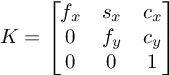
Where f_x, f_y represent focal lengths in pixels. The parameters c_x, c_y denote the position of the principle point in the image coordinate system, the unit is pixels. The parameter s_x specifies the skew parameter.
In the image coordinate system (0,0) corresponds to the center of the upper left pixel:
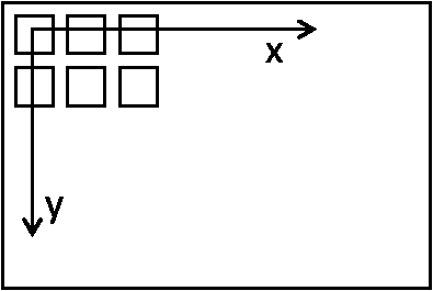 |
Image coordinate system |
The interior orientation parameters of the camera are represented in the .ori format by:
$IntOri_CameraMatrix | K |
$IntOri_SensorSize | Image width, image height (pixels) |
$IntOri_PixelSize | Pixel size in mm |
$IntOri_FocalLength | Focal length in mm. |